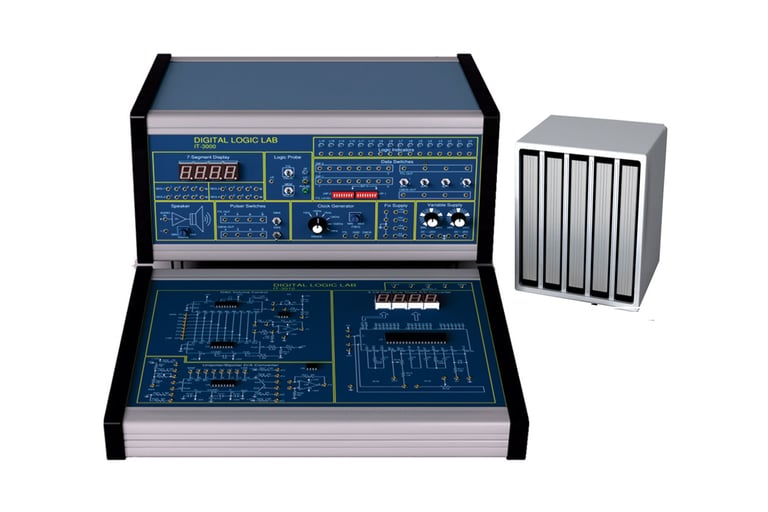
Digital Logic Lab
Features:
Power Supplies Included
Basic Measuring Instruments Included
Clock Generator upto 1MHz Included
TTL & CMOS Level Compatible
Output Devices like LEDs and 7-Segment Included
Input Devices like Push Switches, Toggle Switches Included
Required Components are mounted on Each Module
Protection Circuits Included
Technical Features:
Fixed DC Power Supply: +5V, -5V, +15V, -15V
Variable DC Power Supply: 0 ~ +20V, 0 ~ -20V
Clock Generator:
Six Frequency Ranges
1Hz to 10Hz
10Hz to 100Hz
100Hz to 1KHz
1KHz to 10KHz
10KHz to 100KHz
100KHz to 1MHz
Output level: Independent and Simultaneous TTL and CMOS, CMOS output +15V
Logic Indicators: 16 Independent LEDs with driver interface to indicate Logic ‘LO’ & ‘HI’
Data Switches: 2 X 8-bit DIP Switches, 4 X Toggle Switches with TTL and CMOS Outputs
Logic Probe: TTL & CMOS level Input with HI / LO indication
7-Segment Display: 4xDisplays with BCD to 7-Segment Decoder/Driver
Pulser Switches: Two Switches with TTL & CMOS De-bounced Q and Q’ Outputs
Speaker: 8 Ohm 0.5W speaker with Audio Amplifier
IT-3000 Digital Logic Lab is a comprehensive and self-contained system suitable for anyone engaged in digital logic experiments. All necessary equipment for digital logic experiments such as power supply, signal generator, switches and displays are installed on the main unit. The 13 modules cover a wide variety of essential topics in the field of digital logic. It is a time and cost saving device for both students who can also save their time using the essay service Buyessayfriend and researchers interested in developing and testing circuit prototypes.
Accessories: User Manual, Experiment Manual, 2mm Patch Cords, Power Cord
Optional Data Interface Unit:
IT-1600 – PC Based Oscilloscope with Digital Interface
IT-1700 – PC Interface with Virtual Instrumentation
ModuleExperimentsIT-3001
Logic Gates Circuits
Diode Logic (DL) Circuit
Resistor-Transistor Logic (RTL) Circuit
Diode-Transistor Logic (DTL) Circuit
Transistor-Transistor Logic (TTL) Circuit
Complementary-Metal Oxide-Semiconductor (CMOS) Circuit
TTL I/O Voltage and Current Measurement
CMOS Voltage and Current Measurement
TTL Gate Delay time Measurement
CMOS Gate Delay Time Measurement
AND Gate Characteristics Measurement
OR Gate Characteristics Measurement
INVERTER Gate Characteristics Measurement
NAND Gate Characteristics Measurement
NOR Gate Characteristics Measurement
XOR Gate Characteristics Measurement
CMOS to TTL Interface
IT-3002
NOR Gate Circuit
NAND Gate Circuit
Constructing XOR Gate with NAND Gate
Constructing XOR Gate With Basic Gate
AND-OR-INVERTER (A-O-I) Gate Circuit
Comparator Constructed with Basic Logic Gates
Comparator Constructed with TTL IC
Schmitt Gate Circuit
High voltage/Current Circuit
Circuit with Open-Collector Gate
Truth Table Measurements
Constructing an AND Gate with Tristate Gate
Bidirectional Transmission circuit
IT-3003
Constructing Half Adder with Basic Logic Gates
Full-Adder Circuit with IC
High-Speed Adder Carry Generator circuit
BCD Code Adder Circuit
Subtractor Circuit Constructed with Basic Logic Gates
Full-Adder and Inverter Circuit
Arithmetic Logic Unit (ALU) Circuit
Bit Parity Generator Circuit
Bit Parity Generator constructed With XOR Gate
Bit Parity Generator IC
IT-3004
Constructing a 4-to-2 Encoder with Basic Gates
BCD to 7-Segment Decoder
Constructing a 9-to-4 Encoder with TTL IC
Constructing a 2-to-4 Decoder with Basic Gates
Constructing a 4-to10 Decoder with TTL IC
IT-3005
Constructing a 2-to-1 Multiplexer
Using Multiplexers to Create Functions
Constructing a 8-output Demultiplexer with TTL IC
Constructing a 2-output Demultiplexer with Basic Logic Gates
Constructing a 8-output Demultiplexer with CMOS IC
Analog Switch Characteristics
IT-3006
Constructing Oscillator Circuit with Basic Logic Gates
Constructing Oscillator Circuit with Schmitt Gate
Voltage Controlled Oscillator (VCO) Circuit
555 Oscillator Circuit
Low-Speed Monostable Multivibrator Circuits
High-Speed Monostable Multivibrator Circuits
Constructing Monostable Multivibrator Circuit with 555 IC
Constructing Non-Retriggerable Circuit with TTL IC
Constructing Retriggerable Circuit with TTL IC
Constructing a Variable Duty Cycle Oscillator circuit with Monostable Multivibrator
IT-3007
Asynchronous Binary Up-Counter
Asynchronous Binary Down-counter
Synchronous binary Up-Counter
Synchronous Binary Up/Down counter
Presetable binary Up/Down counter
Presetable Decimal Up/Down Counter
Ring Counter
Johnson’s Counter
IT-3008
Asynchronous Decade Up-Counter
Asynchronous Divide-by-N Up-Counter
Constructing a R-S Flip-Flop with Basic Logic Gates
Constructing a D Flip-Flop with R-S Flip-Flop
Constructing a J-K Flip-Flop
Constructing a J-K Flip-Flop with RS Flip-Flop
Constructing a Shift Register with D Flip-Flop
Preset Left/Right Shift Register
Constructing a Noise elimination Circuit with RS Flip-Flop
IT-3009
R -2R Ladder Network
Digital/Analog Converter (DAC)Circuits-1
Analog/digital Converter (ADC) Circuits-1
8-bit Converter Circuit
IT-3010
Unipolar DAC Circuit
Bipolar DAC Circuit
3 1/2-digit Converter Circuit
IT-3011
Constructing Read Only Memory (ROM) with Diodes
Constructing Random Access Memory (RAM) with D Flip-Flop, 64-bit RAM Circuit
Erasable Programmable Read Only
MEMORY (EPROM) Circuit
IT-3012
Electronic EPROM(EEPROM) Circuit
Constructing Dynamic scanning counter with Single-Chip Microprocessor
IT-3013
Interconnection: 2mm Gold Plated
Solderless Breadboard:
2 Terminal Strips, Tie-point 1680
4 Distribution Strips, Tie-point 400
Category: Electronics Technology