Energy Losses in Pipe Apparatus
Experiments
Measurement of the pressure loss for laminar flow.
Measurement of the pressure loss for turbulent flow.
Determination of the critical Reynolds’ number.
Measurements using a bank Manometer.
Investigate pressure losses at segment bend and bends.
Pressure losses at contraction and enlargement.
Determination of simple valve characteristics.
Specification
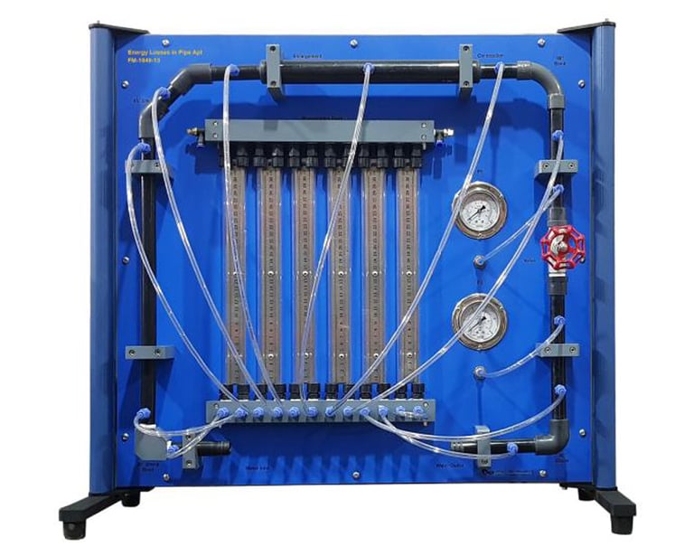
Experimental set-up for the investigation of pipe friction, for use with the Basic Hydraulics Bench or lab water connection.
Bends expansion and contraction, elbows and gate valve with manometer bank on Bakelite base on aluminum structure frame.
Manometer bank for measuring pressure drop in fitting, elbows, bend etc. made easily and measuring individually.
Technical Data
Parts
Pipe diameter: 17mm (inner)
Outer Diameter: 21mm
Enlargement pipe diameter: 26mm (inner)
Outer Diameter: 32mm
Contraction diameter: 17mm
45o elbow, 90o elbow
Sharp bend, Small bend
Contraction and enlargement
12 tube manometer bank
Measuring range
Water Tube Manometer – up to 12 tubes
Multi-tube 300mm of WC
Pressure Gauge
Gauge 2pc
Required for Operation
Hydraulic bench (closed water circuit) or laboratory
water connection
Scope of Delivery
1 experimental unit
1 instruction manual
1 set of hose piping
1 stopwatch
Category: Fluid Mechanics Products
The experimental set-up can be used on its own or with the Hydraulic bench. A supply of water is all that is required for operation. The unit is suitable for measuring pipe friction losses for laminar and turbulent flows. The experimental set-up is clearly laid out on a training panel. For investigations on laminar flow and for turbulent flow, the supply is provided via the Basic Hydraulics Bench directly (or the lab water mains). The water flows through a pipe section; the flow is adjusted using reducing valves. The connection to the required measuring device is made via pressure tapings.