Pelton Turbine Apparatus
Experiments
Principle of operation of a Pelton wheel turbine.
Characteristic at constant head
o Relationship between torque and speed
o Efficiency dependent on speed
o Flow rate dependent on speed
o Hydraulic power and mechanical power dependent on speedEvaluation of measuring values and characteristics based on the theory.
Partial load behavior with needle
control in comparison to throttle control.
Specification
Turbine to place upon the base unit.
Functioning and operating behavior of a Pelton turbine.
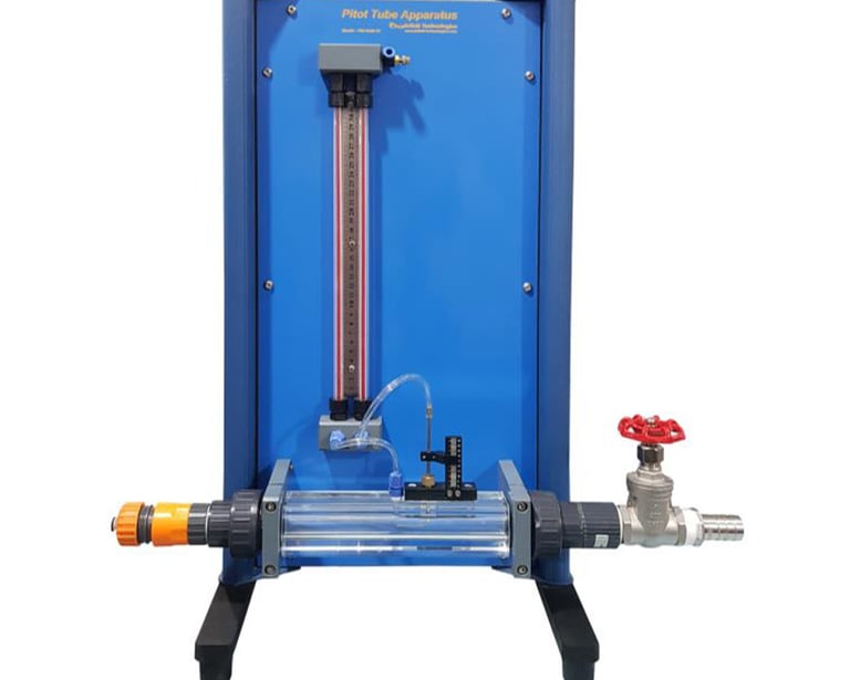
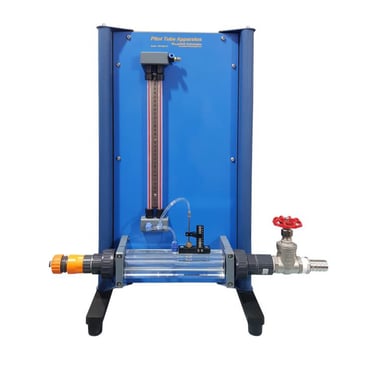
Transparent housing for observing the Pelton wheel and spear nozzle.
Different nozzle cross-sections via adjustable nozzle spear.
Constant pressure of the turbine represents in practice the head and is adjusted via base unit.
Turbine load using the wear-free and adjustable eddy current brake. (optional)
Force sensor to determine the torque on turbine shaft. (optional)
Optical speed sensor for measuring the turbine speed. (optional)
Water supply, flow rate measurement and unitspecific software data acquisition and operation via base unit. (optional)
Technical Data
Pelton turbine
Power output: approx. 30W at Max.1800RPM
Wheel diameter: 150mm
Measuring ranges speed range: approx. up to 4000 RPM
Manometer range: 0 to 4 bar, Number of buckets: 16
Max power: 30W, Max torque: 0.3Nm approx.
Required for Operation
Hydraulic bench (closed water circuit) or laboratory water
connection
Software FM-1849-14SW (optional)
The user-friendly DAQ Software NITM is specifically designed in the NITM Lab VIEWTM environment. It provides a comprehensive solution for data acquisition, processing, and reporting on Windows system. The software empowers users to precisely measure and calculate values, aggregate data into a table graphs, and image. Ultimately, it generates a
comprehensive CSV report that includes all measured and calculated data, including graphs.
Scope of Delivery
1 experimental unit
1 instruction manual
2 force balance
1 tachometer
1 stopwatch
Category: Fluid Mechanics Products
The Apparatus of Pelton turbine mounts on the base. Pelton turbine is mounted on a transparent Plexiglass Hosing. A adjustable water spear valve allow the water to leave through the nozzle and hits the buckets. An adjustable spear valve controls the discharge by varying the diameter of the jet from the nozzle. The Hydraulic Bench supplies water to the nozzle. Water from the turbine discharges back into the base unit tank and recalculates. This demonstration Pelton Turbine is a miniature Pelton wheel with spear valve arrangement mounted on a support frame which locates on the Hydraulics Bench top channel.
Mechanical output from the turbine is absorbed using a simple friction dynamometer. Pressure at the spear valve is indicated on a manometer gauge. A non-contact tachometer may be used to determine the speed of the Pelton wheel turbine. Basic principles of the Pelton wheel turbine may be demonstrated and with appropriate measurements, power produced and efficiency may be determined.